
pusheenz40 (how I found the perfect SMD key switch)

Purpose:
Talk about my latest keyboard, the pusheenz40, as well as the SMD switches it uses. Addtionally cover the design process to make keycaps for the SMD switches.
Problem:
My last pocket keyboard, the modkipz40, was a board that I was fairly satisfied with. It was both pretty comfortable on my wrists, and looked pretty decent as well. However, it still had a minor pain point of the kailh mute switches I was using. The switches were a bit tricky to type on given their small size, and a bit uncomfortable to type on as well for prolonged periods of time. It also made the board a tad bit thicker than I thought it could be.
Ideally, I could make something that was a bit thinner and a bit more confortable to use. Initially, the idea of having the keyboard just consist of a pcb and be the thickness of a credit card also excited me.
Solution:
When browsing for potential mouse switches to use for my pocket boards, I stumbled upon the panasonic EVQP0N02B, an SMD switch that was used in some Microsoft and Xiaomi mice.

This switch really interested me because it was low profile, SMD, and available on LCSC. It being low profile meant I could have a board that was ultra thin as the switches would no longer be the limiting factor. It being SMD meant that I also didn't have to worry about the pokey through hole bits, which take up vertical space (and also opens the door to having, say, a lipo battery on the other side of the pcb). It being on LCSC meant I could hypothetically have a "zero-assembly" keyboard since it could just be assembled for me through JLCPCB. This biggest downside on paper was that the durablility rating for these switches was only 1 milion actuations, which is 2 million less than what's stated for kailh mute switches. I still thought that 1 million was both considerably more than other tactile switches, and should be sufficient for the sake of this keyboard, assuming the lifetime of this board goes down to maybe a couple of years of frequent use.
I basically took the modkipz40 pcb, swapped in the smd footprint in, and sent the order off to JLCPCB. This meant the keyboard would still be using the awesome STM32F072C8Tx MCU
Initial Thoughts:
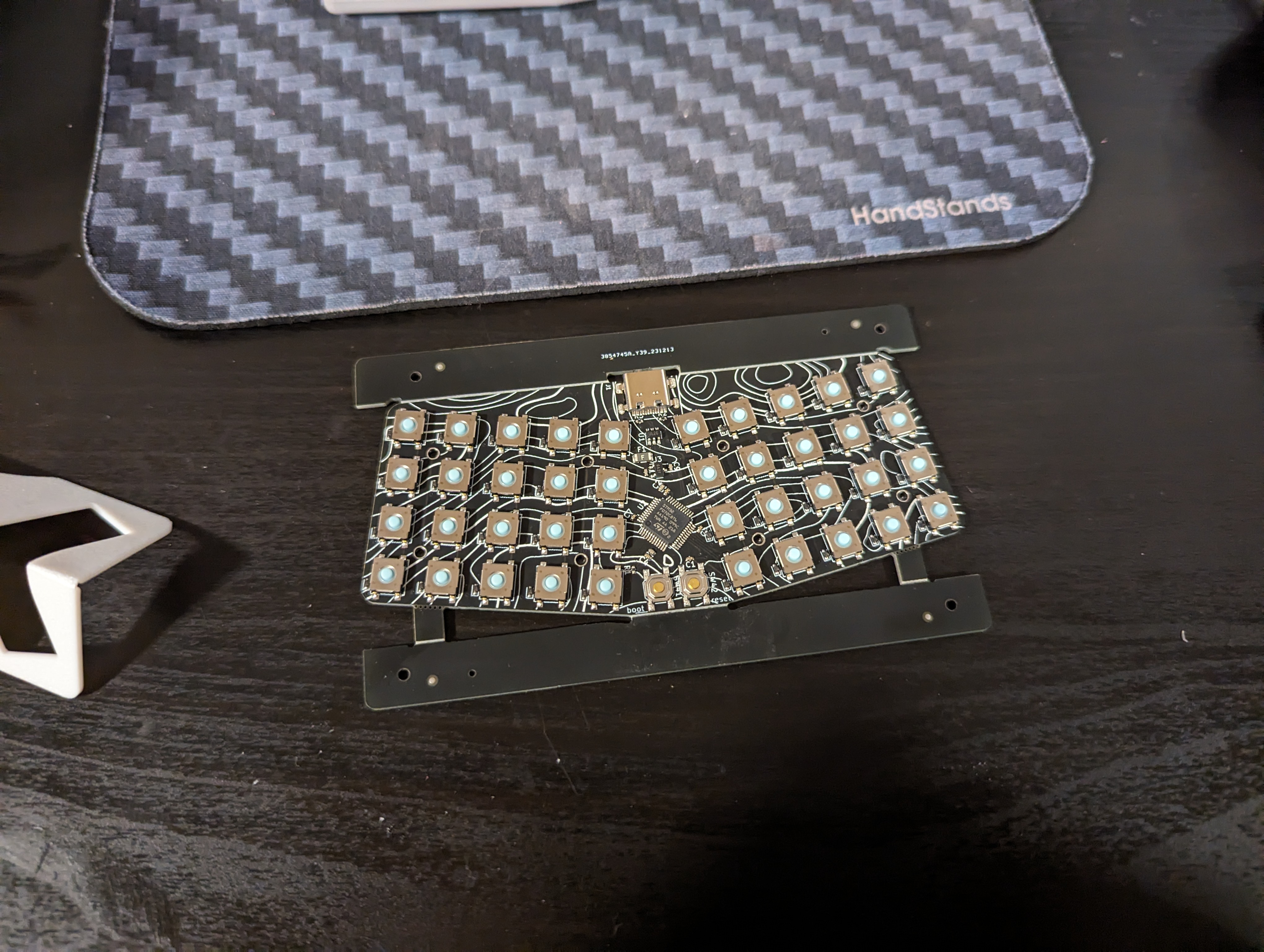
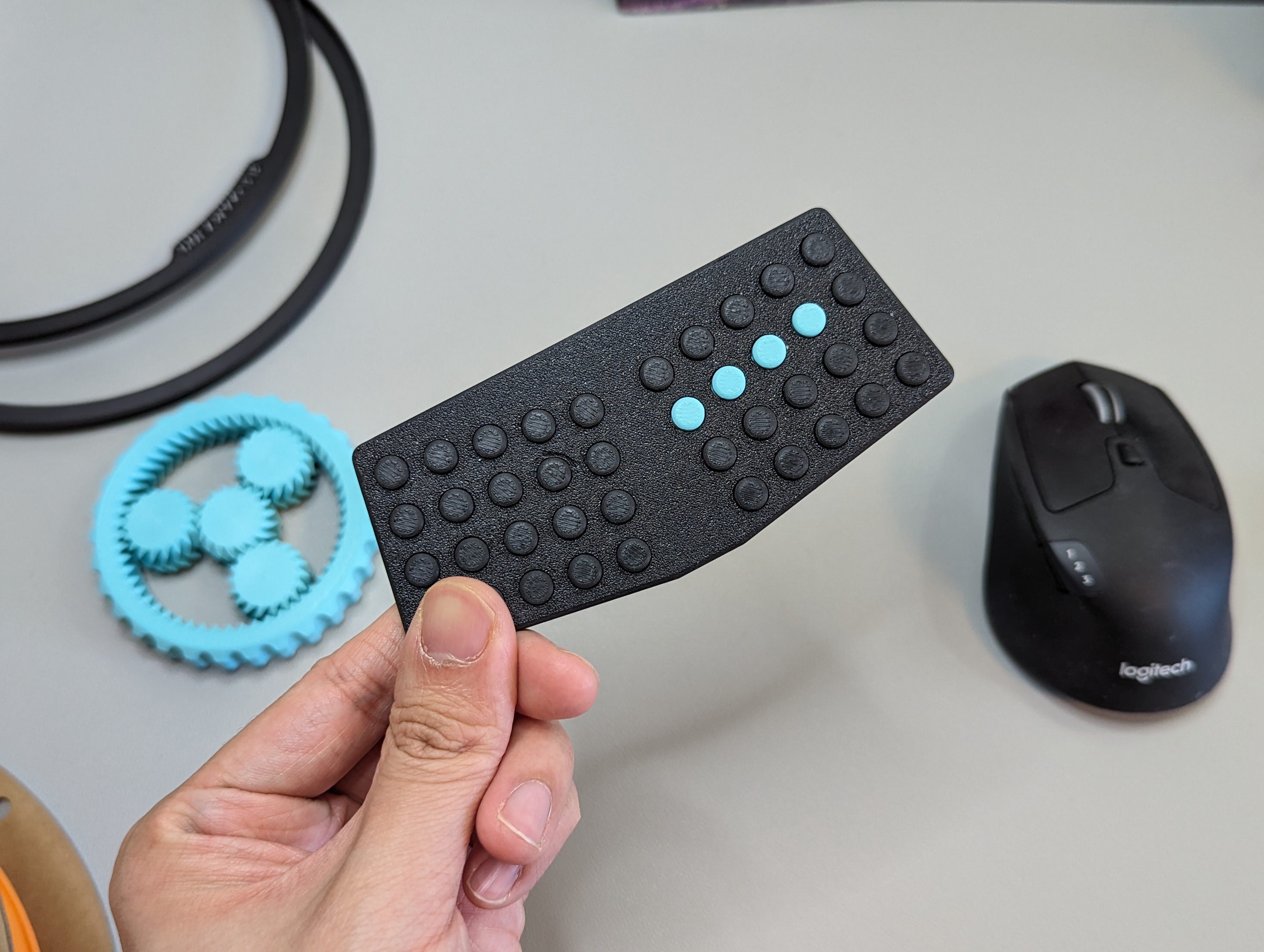
I was pretty excited when the pcb came in! I added a topology graphic to the pcb's silkscreen, and I thought it looked pretty nice! I was exited to try the keyboard pcb as-is, in the hope of having an ultra flat creditcard thickness board. However, I got pretty disappointed when trying to type on the board. I got roughly words per minute in the 30s in monkeytype, which was less than half then that of what I get with the modkipz40. Worse yet, the thumb keys hurt like crazy, since my thumbs ended up jamming into the sharp metal corners of the switches more often than not. It was clear to me that as-is, this board wouldn't be viable, and that I would have to add some sort of keycap to make typing on this possible
Developing custom keycaps:
In my initial attempts of the bunchiez40 and modkipz40, I had tried to make my own 3D printed buttons to go ontop of of the kailh buttons. The biggest issue by far is that these switches have no keycap stem, so there's no easy way of attaching any form of keycap onto the switche. Other big issues was that it was really difficult coming up with a design that was easily 3D printable, and reliable. I had several iterations of switches that were joined together to the keyboard case, and used some form of compliant mechanism as a means of movement. All iterations ended up failing for several reasons, some of them being that they introduced too much height to the board, or because they were near impossible to produce well. I ended up abandoning the idea in favour of typing on the kailh switches directly.
During my research process, I wanted to figure out how a kailh mute switch acutally worked, and tore one down.
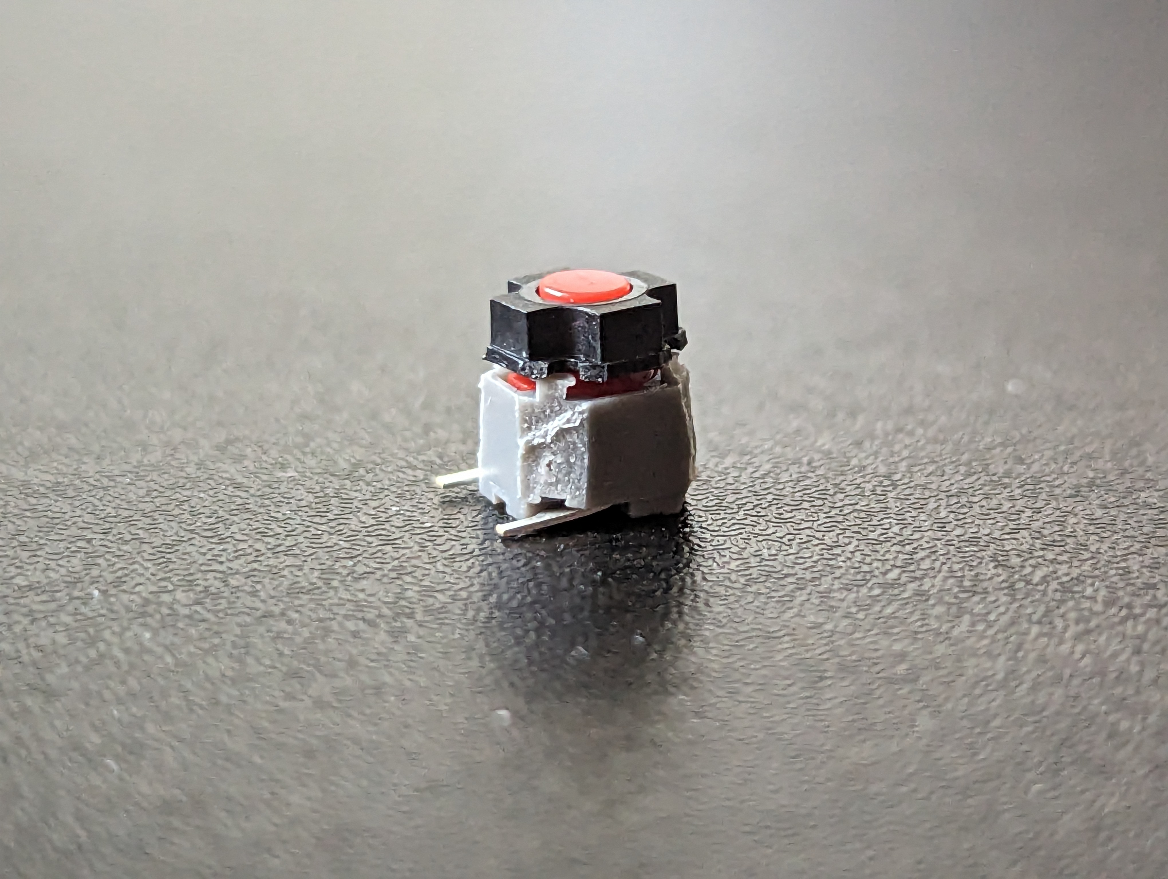

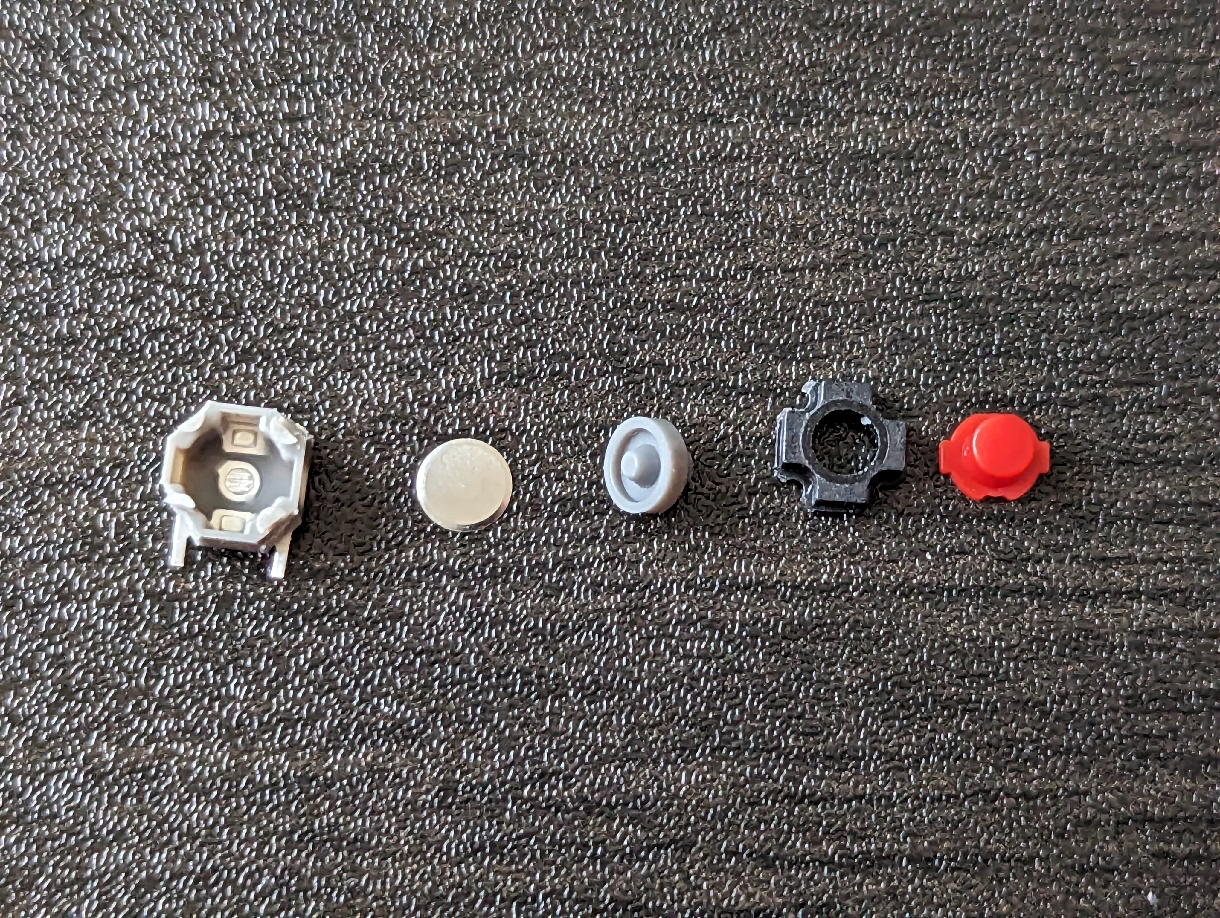
The teardown proved to be exceptionally informative, since it broke down what was required for a switch of this size. As seen in the third picture, the red "cap" has a sliding piece sticking out that slides along the rails of the grey body, and is held in place by the black top case. The red cap can depress the grey silicon membrane, which can cause the metal disc to collapse in to make an connection with the two metal leads. These components are very similar to that of the joycon buttons as well.
The most interesting observation in my mind was that the SMD buttons I had effectively act as the bottom 3 components of the switch. If I designed and added my own caps and top housing, then I'd effectively have my own "complete switch" that should be much easier to type on. The best part is that if I make the cap and top housing myself, I can tweak it to my liking, and tune it's size and height to my hearts content.
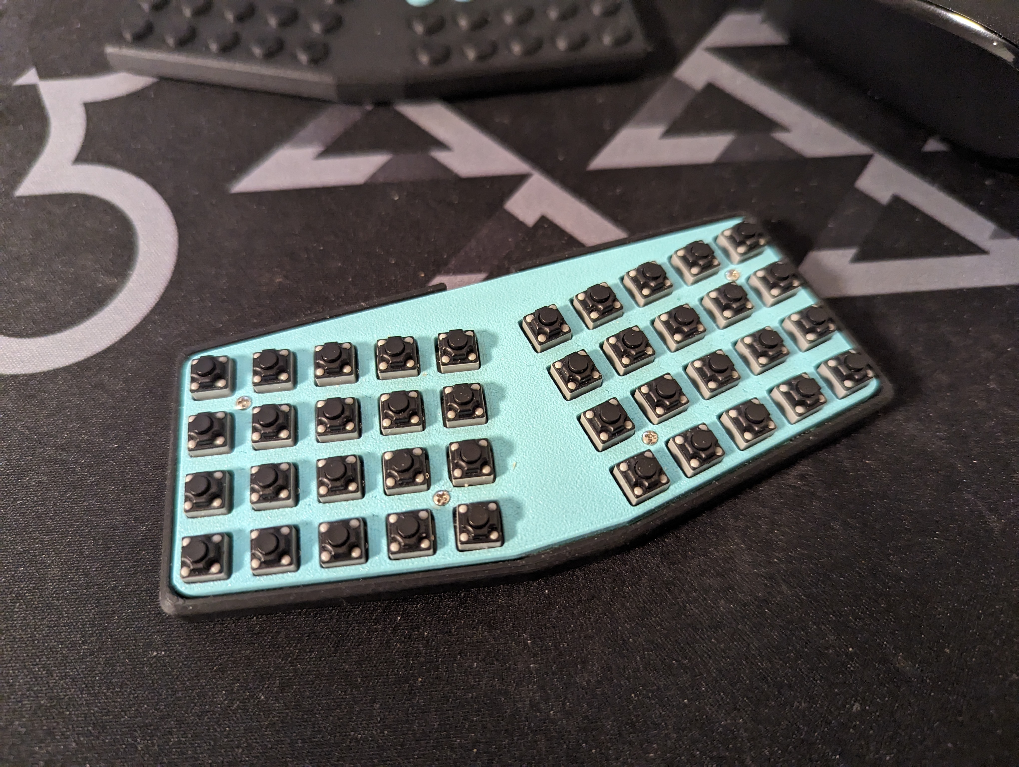
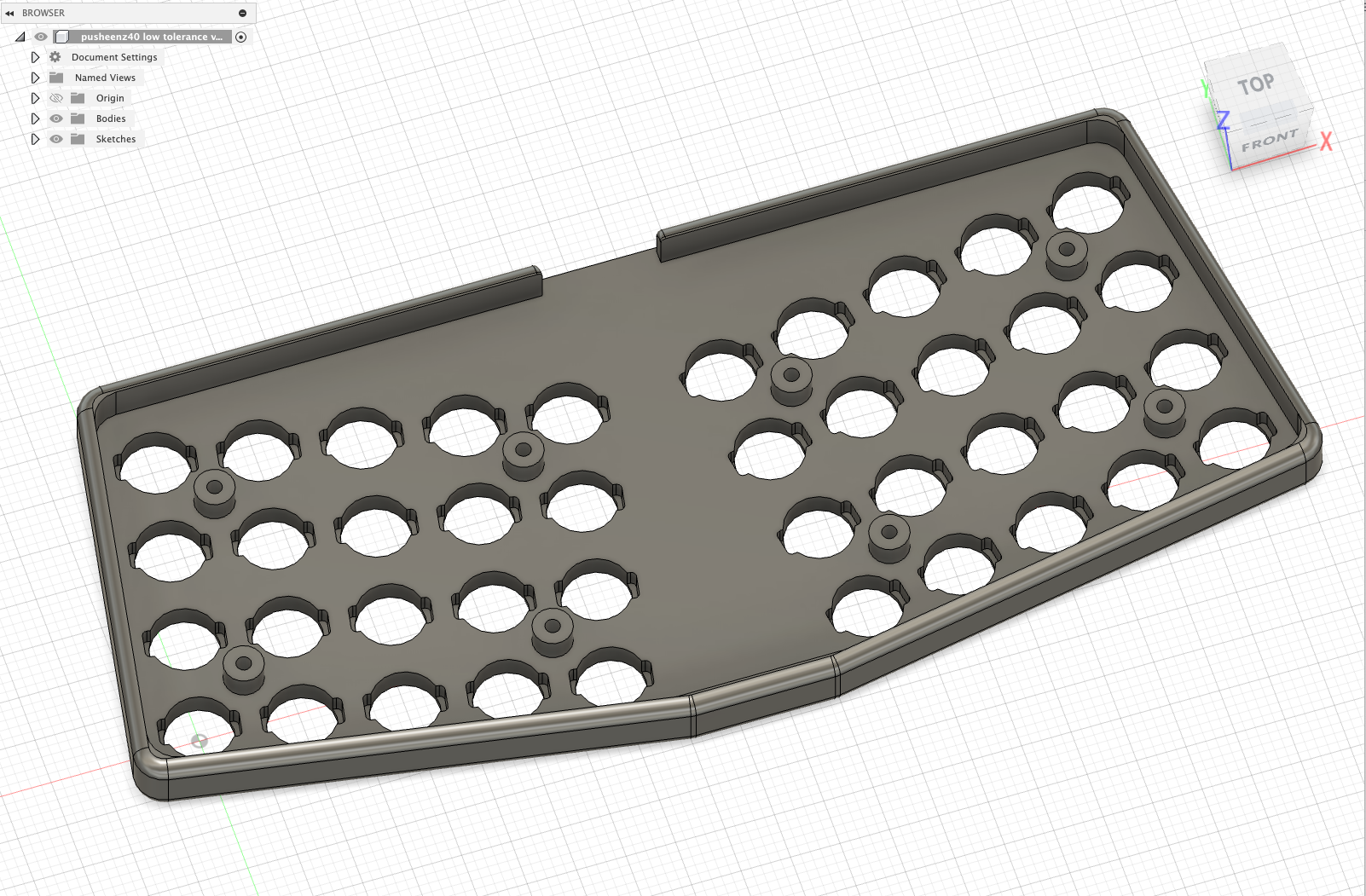
I used ergogen to make a new case for my board. Most notably, I added in "slider rails" to my cases integrated plate, so that the entire top plate could act as a slider and a top housing for my switches. From there I made caps similar to that of the kailh mute switch: generally cylindrical with knubs on each end that could fit into the sliders.
Results:
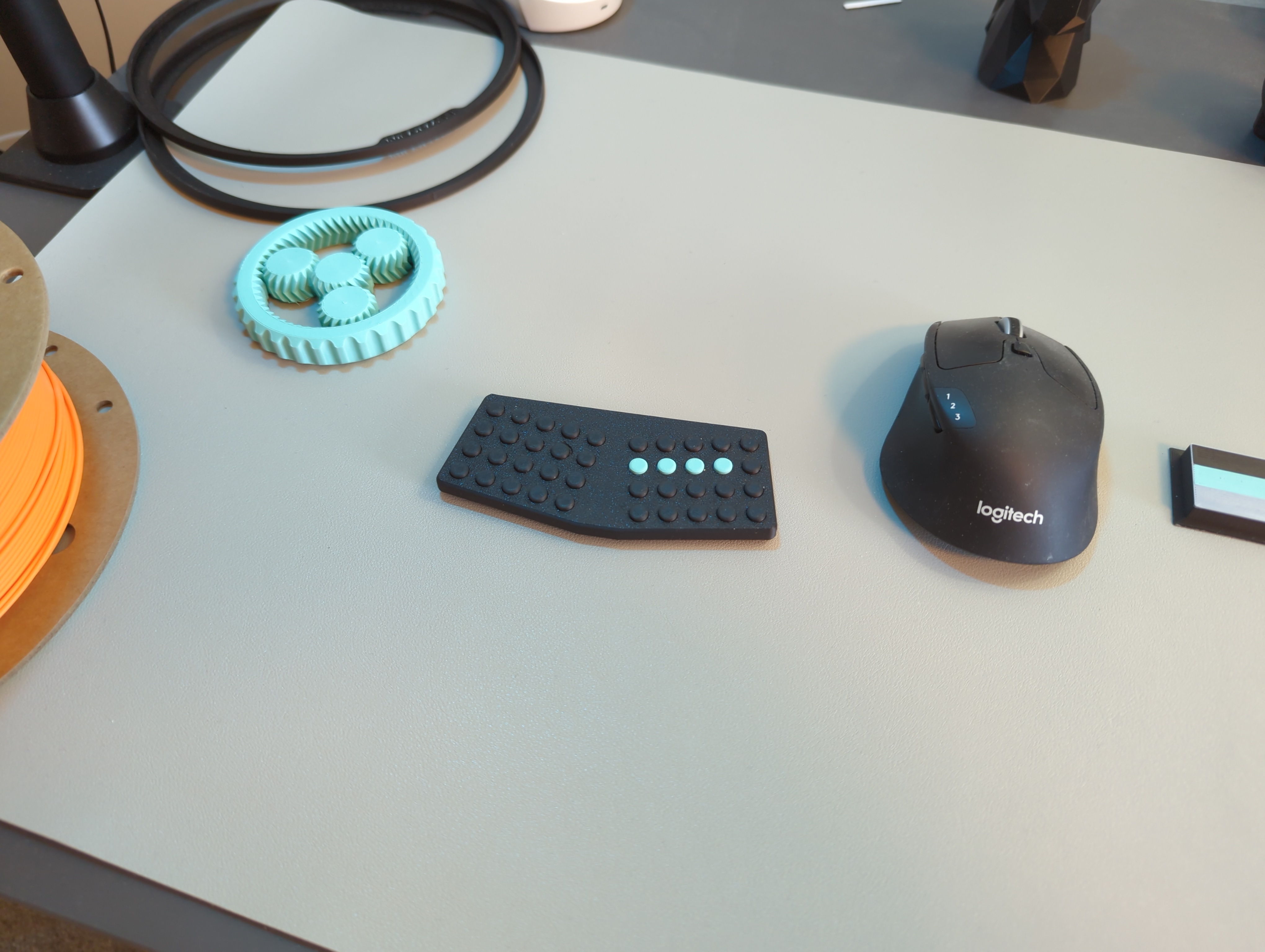
After several iterations of refining the tolerances, such that the keycaps were neither sticky nor needlessly wobbly, I was able to make something I'm very happy with! I had to use the finest settings on my P1S 3D printer, but I was able to make something that was both very comfortable and relatively easy to type on! My fingertips no longer hurt and my wpm was able to spring back to to 80+ wpm. I was even able to get 100+ wpm on this board.
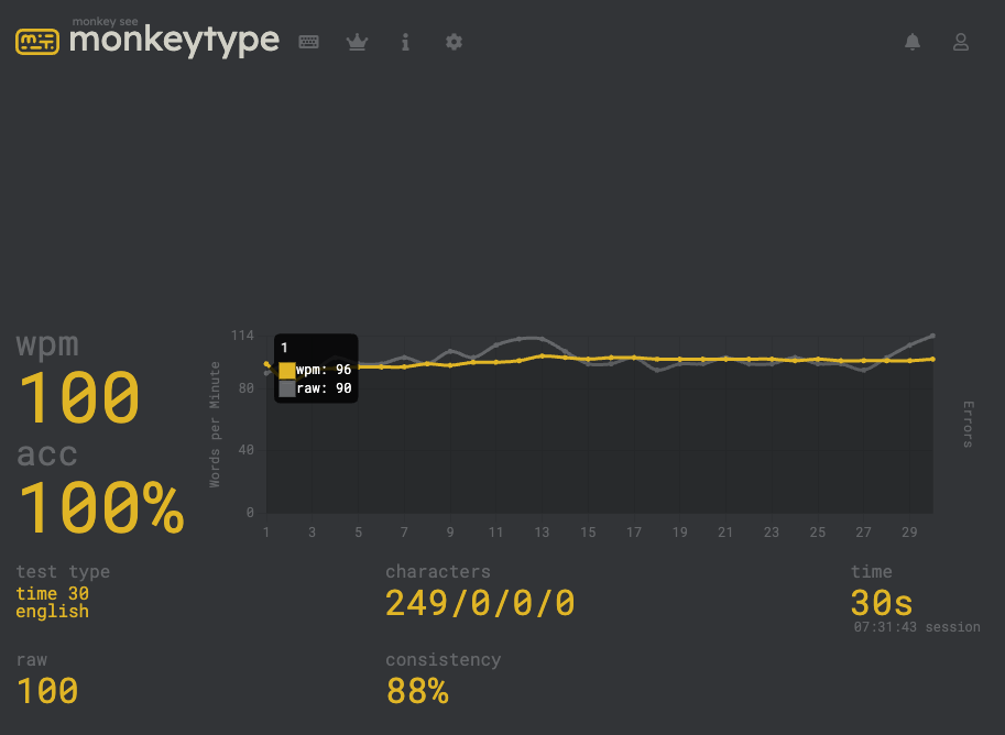
The screenshot itself isn't definitive proof for a skeptic, but you'll have to take my word on this one until I do a proper typing test :). I hope the image atleast is illustrative that typing on this board is viable for daily driving.
The board is also super thin at around 8mm. In fact, it might almost be too thin given that a small part of my wrist bone rubs against my desk a bit. Not enough to cause carpel tunnel strain, but enough that I wouldn't mind if I went a couple millimeters higher.
Future Plans:
I think the idea of SMD switches is really exciting, since it opens up a ton of real estate on a pcb, and can reduce a lot of work required assembling a board, since it can mean that no soldering is required. The two most interesting projects that could result from this is either a board with a lipo at the back of it, or a board that's cheap and easy to produce and distribute.
Acknowledgments:
Huge thank you to BeeKeeb, TALPKEYBOARD, and kurihara for sponsoring me on Github and ko-fi!! These fun experimental builds wouldn't be possible without your generous support, and let me keep pushing the boundaries of keyboard design. If you found this project interesting or informative, or like to see me make more projects similar to this, please consider supporting me on Github or ko-fi!